| Technical Support and Information | |||||
| How can I locate the coil voltage on a Eaton XTCE contactor? | |||||
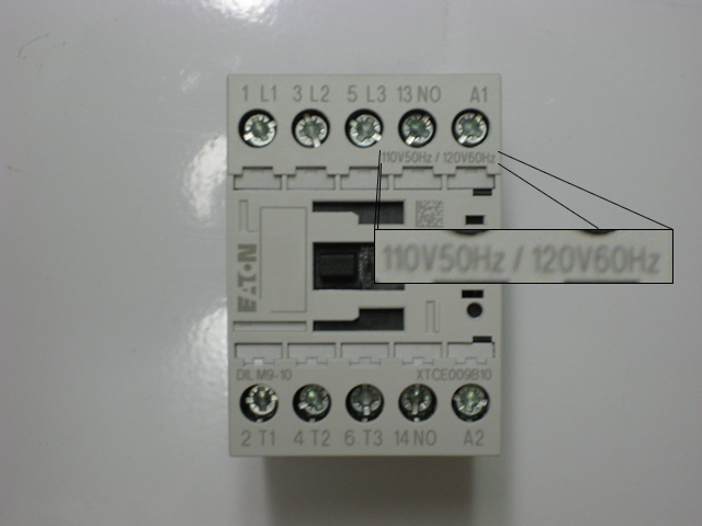
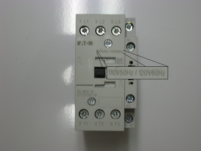
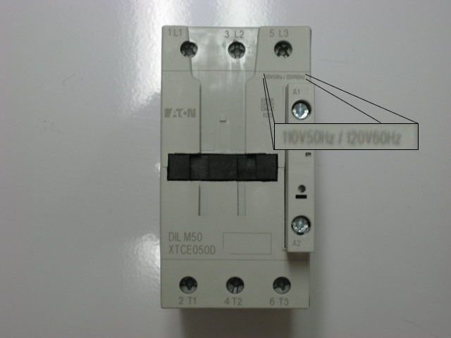
Eaton's new line of XTCE contactors is replacing the old line of Moeller DILM contactors and is one of the best, longest lasting IEC rated contactors in the industry. To determine which contactor you will need there are two main components that are necessary to create the part number. First you have the part number which starts with a XTCE. For example you might have a XTCE009B10 or a XTCE050D, and both part numbers tell the size of the contactor along with the contact arrangement. Next you will need the coil voltage which is located toward the top of the contactor. In the pictures below you can see where the coil voltage is located. Click to enlarge any picture:
Once you have these two pieces of information you can determine the exact complete contactor number. Each coil voltage has a code that is not listed on the contactor but helps complete the part number. So another example would be a XTCE040D with a 24v50/60Hz AC coil. The complete part number is a XTCE040D00T, where the XTCE040D tells the size of the contactor, the 00 shows that there are no auxiliary contacts on the contactor and the T designates a 24 volt AC coil. Note: Each contactor has a specific coil voltage so please ensure choosing the correct one prior to ordering. For any questions please contact us at [email protected]. |
|||||
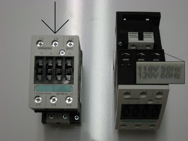
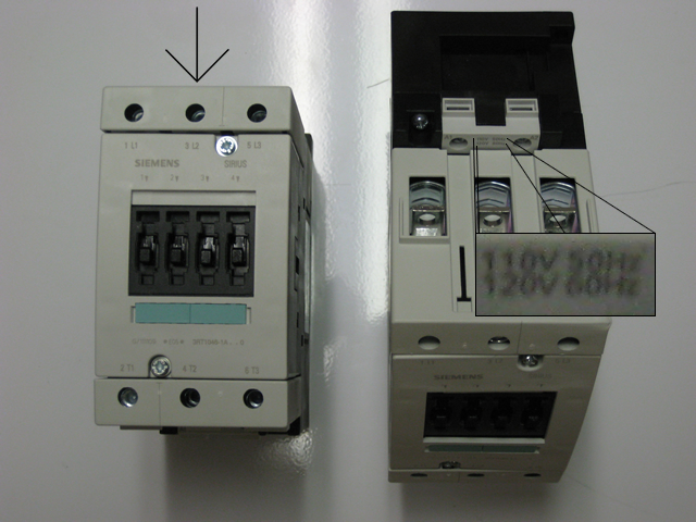
| How do I find the coil voltage on my Siemens 3RT contactor? | |||||
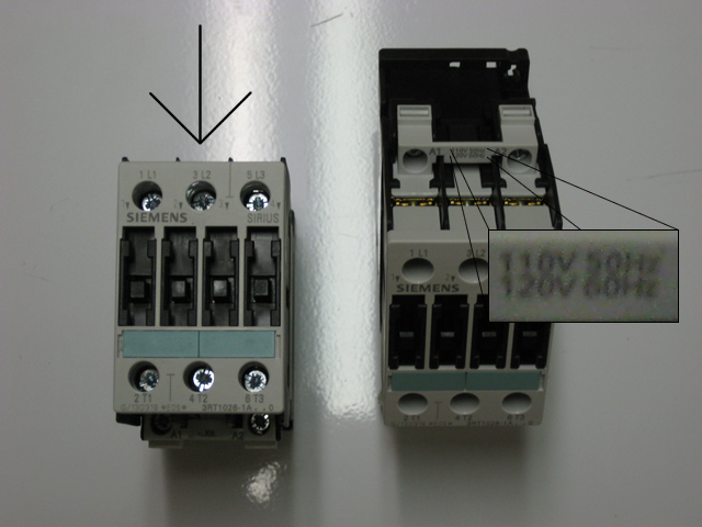
Each Siemens 3RT contactor is comprised of four basic parts: the plastic outer housing which holds all of the parts on the contactor, the contact set (usually three separate moving and six fixed contacts), the armature which transmits the voltage through the contactor and the coil, which pulls the contactor in and actuates its power. On the front of each Siemens contactor is the contactor part number but it some instances, for example in size S0 to S12, the coil voltage is not listed on the front. For the smallest contactors it is simple as the complete part number is on the front of the contactor, such as a 3RT1017-1AK61. But for all other sizes the coil voltage is not listed on the front, but rather on the top of the contactor. You might see a part number such as 3RT1044-1A..0 on the front but this does not tell you the actual coil voltage. A few examples can be seen in the images below:
Note: Please make sure you verify the coil voltage as an incorrect coil voltage will cause the contactor to malfunction immediately and burn up voiding any possibility for return ot warranty. For any questions please contact us at [email protected]. |
|||||
| How do you determine the appropriate class for an overload relay? | |||||
Before we try to determine which type of Class overload you would need, let's first discuss the main types of tripping classes and how they operate. There are four main types of tripping classes: Class 5, Class 10, Class 20 and Class 30 with Class 10 and Class 20 being the most common. Simply put the class of overload you choose determines the number of seconds the overload will trip after it determines there is an overcurrent situation. So for example, in a Class 20 overload relay, the overload relay will wait to trip for 20 seconds after it receives an overcurrent reading before tripping. Once the motor has cooled to an acceptable temperature, the overload will reset. An example of the trip curve tripping times can be seen below: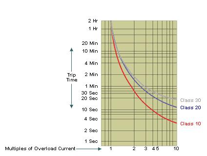 So why the different trip classes? Well you would want to select a trip class based on your application. For general use applications, you would want to use a Class 10 or Class 20. Keep in mind there are two factors to consider: a low class, such as a Class 5 or Class 10 might cause nuisance tripping while a higher class, such as a Class 20 or Class 30, might damage your motor if it is locked and overheating for too long a period of time. The number one priority of an overload relay is to protect the motor, so choose your class wisely. Should you have any questions, feel free to e-mail us at [email protected]. |
|||||
| What is the difference between and automatic and manual reset on an overload relay? | |||||
| Most thermal magnetic and soild state overload relays today come with the option of a manual reset or automatic reset. So which one should you choose? Well let us take a look at the two options and how they behave. Manual Reset A manual reset obviously has to be reset manually. This is the recommeded reset option as if your overload does trip, there is obviously something wrong with the motor as it is in a overcurrent or locked position and it needs to be examined. The manual reset prevents the starter from engaging until the user fixes the problem and resets the relay, thus preventing any further damage from happening to the motor. Automatic Reset A automatic reset will restart the motor once the relays contact have cooled to normal operating temperature. BEWARE: The overload has tripped because there is a problem within the application that needs to be resolved. Not resolving the issue could potentially burn up your motor. For example, if you have a Class 20 overload, generally in a locked rotor position the overload relay will take up to 20 seconds to trip. Once the contacts have cooled, the overload will engage and restart he motor. If the motor is still in a locked rotor state, the overload will wait up to 20 seconds to trip again. This causes stress on the motor that can lead to failure. |
|||||